Costantino is a software that implements the CNC functionalities developed by ISAC. Thanks to 40 years of experience in this field of CNCs and related applications, Costantino maintains all the functionalities of a hardware CNC without the limitations imposed by that architecture It can be installed in every PC or IPC not supplied by ISAC and its characteristics make it ideal for CNC applications that need an on-board CAM and for those who want to offer their own hardware solution while supplying a robust product.
Costantino can be directly connected with Modbus, OPC server and SSI. Otherwise, ISAC can supply also an hardware device, the EtherCAT Bridge, that allows the interfacing of mixed hardware, EtherCAT and other fieldbuses among which. Mechatrolink and CANopen, together with standard interfaces, pulse/direction and analog, with Stepper servodrivers and motors.
Gateway to:

Available connections for IIoT

This solution, contrary to many other products on the market, allows the users to build simple applications based on a standard office PC, while maintaining all the functionalities found only in high-level hardware-based CNCs. For these reasons:
- it is expandable and includes 5-axes machining functionalities and high-speed machining capabilities;
- it includes multi-channel functionalities with many simultaneous part-programs: each channel can control axes in interpolated motion, independent axes dedicated to auxiliary functions as tool change;
- it handles up to 12 axes for each channel;
- it allows to build applications that join execution speed with machining precision, without any limits to the resolution of the measuring systems;
- the PLC can be modified to suit the needs of every application.
Costantino includes a PLC environment, programmable with standard languages that simplify the application and make the learning curve easier:
- languages belonging to IEC61131:
o IL (Instruction List)
o ST (Structured Text)
o LD (Ladder Diagram)
o FBD (Function Block Diagram)
o SFC (Sequentiale Functional Chart)
- ANSI C.
Costantino can control the motion of positioning and coordinated-motion axes through functional blocks in compliance with the PLCopen MC part 1 v. 1.1 specification.
The Costantino CNC environment is ISO6983 compliant (see below G-code list): in other words, the program syntax is very similar to that of other numerical controls. Post-processors for the main CAMs on the market are also available (see compatible CAM list below).
Extensive software application libraries are available that reduce to a minimum personalization needs; however, Costantino is also an excellent basis for developing personalized applications. Applicative software are available that make Costantino CNC ready to be used on different types of machines in different applicative fields with a consequent reduction of project costs.
Costantino CNC includes functionalities and interface components useful in all applications.
The evolution of CNC is the result of a great applicative experience in many fields such as:
In addition, many Ready to Work products come from Costantino:
- Engraving
- Router
- Thermal cutting with Plasma & Oxy
- Thermal cutting with Waterjet machines
- Thermal cutting with 5 Axes Waterjet machines
- Glass cutting
- Wood lathe
- Turning machines
- 3 axes polishing machines
- Bridge milling machines
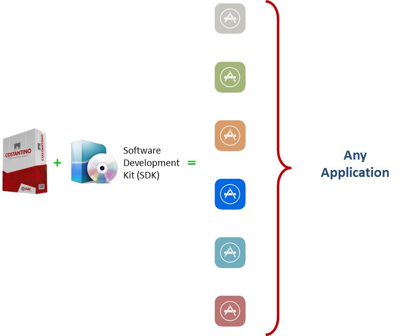
Any Application
- click to enlarge -
Configuring Costantino
Configuring Costantino hardware and software setup is very easy: you can find some example configurations in the “Experience” pages of this website.
Costantino CNC consists of software and an hardware. The software can be composed by two separate modules: the first is the basic CNC software, the second is an applicative software dedicated to specific machines (refer to Ready-to-Work applications). The hardware part consists in a dedicated device, called Bridge, used to convert the EtherCAT communication protocol into other field bus protocols, or to interface the CNC with servodrivers using Pulse/Direction or analog interfaces. In addition, the Bridge allows the communication between the CNC and the machine using analog or digital signals.
In order to complete the Costantino CNC configuration, you need also a PC and an user interface, composed by display, keyboard and mouse. ISAC can supply all this hardware as industrial-grade components, or you can buy it from third party suppliers. In order to define the Costantino CNC configuration suitable for a specific application, and therefore to order the components you need, you should follow these steps:
- Define what kind of CNC software you need, as there are three different types: one to be used without ISAC hardware, a second one to be used with any of the ISAC Bridge you can find in our catalogs, allowing to use the CNC in any application, either customized or Ready-to-Work, and a third one that requires to use the Bridge model BRIDGE06, to be used when a limited number of axes and I/Os are enough;
- Define what model of Bridge suits your needs, choosing it according to the field bus, servodrivers interface and axes number you need;
- Define the PC (or IPC), according to the computing power required by the application;
- Define the user panel;
- Define the application software, in the case of Ready-to-Work products.
When choosing Customized Application, or you want to customize a Ready-to-Work application, you need to buy (only one time) the software developing environment to program the PLC and the HMI.
To make buying simpler, you can separate the hardware and software supply: software is distributed online, through the dedicated private area of the ISAC website, accessible using the credentials supplied to the user when ordering.
Functionalities
Axes Handling
- Synchronization with PLC-controlled axes
- Mechanical vibrations suppression algorithms
- Closing of space-loop with compensation for position reading delays
- Compensation of following error at constant speed and in acceleration, so accurate that allow to achieve machining movements with following errors smaller than 1um
- Gantry axes, with one master and one slave, or with one master and more slaves, with reciprocal following error control
- Electronic cams between master and slave axes
Spindle
- Programmable with standard ‘S’ and ‘M codes;
- Velocity is programmable in round per minute or in meters per minute (cutting with constant speed);
- Control of 6 speed range;
- Orienting;
- Rigid tapping;
- Threading.
CNC Functionalities
- Up to 8 concurrent part-programs, up to 12 axes for each channel;
- Trajectory control with 512 blocks read forward, analysis of apparent accelerations with jerk control;
- Machining and homing macros defined by the user and that can be recalled from the program;
- High-speed cutting and superfinishing algorithms.
- Roto-translation of the working plane on the space;
- Restart of interrupted machining from any block, with any nesting and program repeatition level;
- Graphical selection of the reprise point and help in ambiguity cases;
- Mechanical operating parts and axes repositioning after having executed different commands from the ones included in the program in execution;
- Retrace: Execution of the machining program in forward and reverse modality;
- Interruption of the current program to execute other programs;
- Trace of the blocks execution and 3D visualization of the path already done;
- Linear, circular, helical NURBS interpolation;
- Electronic handwheels;
- Definition of the speed on the trajectory with constant space, with inverse time, with constant feed on the rotating piece;
- Reconstruction of the geometry from the straight line of the control points and corner chamfering;
- Axis tangent to the trajectory, even with offset drill in respect to the rotation axis;
PLC Environment
- IEC61131 and ANSI C programming languages;
- Multi-task environment for concurrent operations management, even synchronized with the interpolation.
Lathe
- CNC mode switching between Mill and Lathe;
- Constant, increasing or decreasing pitch filleting;
- Programming of toolpath using diameter or radius;
- Spindle Speed and Feed according to the local radius of the piece (G95, G96);
5-Axis Functionalities
- Programming of the path of the tooltip or of the center of the tool and of its orientation (RTCP) for all standard 4, 5 and 6-degree of freedom kinematics.
- Robotic Module Management: execution of the machining program defined on the tool center and on its orientation, on machines with non-standard kinematics, like polar machines, or SCARA, DELTA and PUMA machines;
- Management of inclined tools, with offset in respect to the last joint of the kinematic, like aggregated, offset and manually tilting tools;
- Exit from the piece in the same direction as the tool orientation;
Robotic Module
- Supports any kinematics up to 6 degrees of freedom.
- Supports parametric and conversational programming.
- Supports of mixed programming in joint space or operative space.
- Includes a powerful simulation environment for toolpath test and material removal simulation.
- Conforms to PLCopen MC part 4.
- Supports 5 axis machine tools: SCARA, DELTA and PUMA.
- Fulfills constraints of positional limits, velocity, acceleration and jerk in both joint and operative space.
Watch the Robotic Module in action! Click Here!
CNC Programming
- Definition of the trajectory and cutting technology in ISO6983 code (G-code), through files nested up to 7 levels;
- Instructions for flux control and parametric programming, boolean and arithmetic instructions;
- Over-metal definition;
- Toolpath programming with tool compensation on the left or on the right, with forward analysis of the geometrical interferences between the tool space occupation and the trajectory to follow;
- Functionality of operations synchronization among channels;
- Interactive graphical editor to ease the programming and the immediate verification of syntax and operative conditions;
- Implicit chamfering and transitions.
Simulation
- Part-Program analysis to identify the kinematics limitations that affect the machine performances;
- Graphical representation of the trajectory at the tool center, and simulation of the toolpath;
- Online simulation of material removal with representation of the finished piece, starting from the raw model;
- Simulator of the geometry and kinematics of the machine, with collision analysis between mechanical components;
Installation and Maintenance
- Kinematic chain analysis by means of the integrated oscilloscope function;
- Recording of all occurred events;
- Tele-diagnosis.
Positions
- Cartesian and polar coordinates;
- Absolute and incremental;
- Millimeters and inches.
Tools
- Compensation in the machining plane or space:
- tool length;
- tool radius, with eventual quadrants of belongings included;
- Overall control of tools and planar, rotating, tower and mixed storage systems;
- Management of random tool storage systems;
- Tool wear management with statistic and dynamic update of tool size;
- Management of tool life.
Origins
- 20 origin points + absolute and incremental displacement;
- Piece origin creation by self-learning;
- Tool preset.
Canned Cycles
- Drilling;
- Tapping;
- Slotting;
- Threading;
- Roughing for lathes.
G-codes List
Main G-codes
Code |
Description |
| G0 | Rapid Movement |
| G1 | Working linear movement |
| G2 | Clockwise arc |
| G3 | Counter-clockwise arc |
| G4 | Pause during machining |
| G5.1 | High-speed machining and superfinishing |
| G6.2 | NURBS interpolation (up to 3rd degree) |
| G09 | Precise stop at block end |
| G10 | Polar coordinates: linear interpolation |
| G12 | Polar coordinates: clockwise arc |
| G13 | Polar coordinates: counter-clockwise arc |
| G16 | Selection of contouring plane |
| G17 | XY contouring plane selection |
| G18 | ZX contouring plane selection |
| G19 | YZ contoring plane selection |
| G25 | Limitation of working area: minimum value |
| G26 | Limitation of working area: maximum value |
| G33 | Filleting |
| G34 | illeting at increasing pitch |
| G35 | illeting at decreasing pitch |
| G40 | Disenabling tool radius compensation |
| G41 | Compensate tool radius with good material on the right |
| G42 | Compensate tool radius with good material on the left |
| G43 | Add tool length compensation |
| G44 | Subtract tool length compensation |
| G46 | Tangential detachment from piece |
| G47 | Tangential attack with right side profile |
| G48 | Tangential attack with profile on left |
| G49 | Length compensation disabling |
| G53 | Positions are related to machine physical origin |
| G54 | Working origin selection (up to 50 origins) |
| G58 | Machining origin (relative) translation |
| G59 | Machining origin absolute translation |
| G70 | Programming in inches |
| G71 | Programming in mm |
| G80 | Cancel drilling cycle |
| G81 | Drilling |
| G82 | Spot face |
| G83 | Deep drilling |
| G84 | Forward tapping |
| G85 | Boring cycle |
| G86 | Boring with spindle stop |
| G87 | Boring with oriented spindle stop and detachment |
| G89 | Boring with halt |
| G90 | Programming with absolute position |
| G91 | Programming with incremental position |
| G92 | Limitation of spindle max speed in G95 |
| G93 | Feedrate in time inversion |
| G94 | Feedrate in mm/min |
| G95 | Feedrate in mm/rev |
| G96 | Spindle speed in meters/min |
| G97 | pindle speed in RPM |
Extended
Code |
Description |
| G302/G303 | Transform an axis into an independent / contouring axis |
| G305 | Mirroring |
| G306/G307 | Application of overmetal |
| D0 | Zero the tool leght |
| D1/D2/D3/D4 | Multi-taglient tool radius and lenght #1/#2.#3/#4 set selection |
| G312 | Automatic software limit disable or programming |
| TNG | Tangent axis programming |
| G319 | Transformation Matrix and roto-translation |
| G327/G328 | Shared axis acquisition/release in the current channel |
| G329 | RTCP definition |
| G340 | Interpolation with modulo axis |
| G350 | Milling/lathe mode selection |
Synchronization mechanisms
Code |
Description |
| [!xxxx] | Synch-label (asynchronous communication with PLC) |
| Mxxxx | Auxiliary functions, run in pre-defined sequence with the movement block (synchronous communication with PLC) |
| G318 | Sends a code to PLC |